Discontinuing RV Flap Actuator, Replacing with New RV Max Flap Actuator

We have decided to discontinue the RV Flap Actuator that many have installed in their single-digit RVs, the RV-6, -7, -8, and -9. We are now recommending the RV-10/-14 actuator for all models except the RV-8. This newer actuator will now be renamed the RV Max Flap Actuator.

There are several reasons for doing this. Although there are hundreds of this actuator presently in RVs, we have had a few that will spontaneously retract–typically from full flaps back to about half flaps–for no apparent reason. We have termed this phenomenon “blowback.” It has occurred in about 3 actuators to date that we know of. We have had the factory look at an affected actuator and they have not seen any mechanical problems so our conclusion is that some actuators that are overly lubricated can be forced up. This would seems to be impossible given the nature of the jackscrew operation, but apparently in the case of over lubrication, it is possible to start the motion of the jackscrew by applying a force against the actuator. We had one customer disassemble his actuator and removed some of the lubrication and reported back that the actuator is operating much better. We have had this actuator in our own RV-6 for several years now without any problems of any kind.

Since we introduced the RV-10/-14 Actuator several years ago, we have sold many (over a hundred) to owners of those two aircraft. Given that the RV-9 wing and flaps are very similar, we installed one in an RV-9 build some time back and have had a great deal of success with it in the RV-9. We have since installed a few in RV-7s. We have concluded that this actuator works very well in the single-digit RVs. Additionally, this actuator is much more robust than the previous one and although about $50 more in cost, a much better value considering the high quality of the unit.

Due to supply chain issues, it is becoming more and more difficult to keep both actuators in stock. Going to just one actuator will greatly simplify our logistical problems and help us keep more of the RV Max actuators in stock.

Unfortunately, this actuator is probably not practical in an RV-8 due to its increased length and bulk. It is slightly longer and wider and weighs about a pound more than the older units.

New! RV Flap Actuator–An Improvement Over the Stock Flap Motor

We will soon be introducing our new RV Flap Actuator, which for some folks will be a big improvement over their current flap motor.

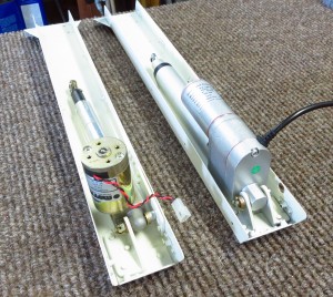
Although not a direct replacement, only minor modifications are necessary either to an existing installation or if building a new installation.  Our Installation & Operating Instructions are available for download and printing here.  We found that the installation in our RV-6 was relatively simple.  We did order a new flap motor channel from the mothership just to facilitate the changeover, but you could modify the one you have.  The majority of the work involves making a couple of new brackets out of 1 1/2 x 1 1/2 x 0.125″ 2024T3 angle.  The actuator is a little over an inch longer than the stock one, so you have to adjust for that.  We were able to move the attach point back about an inch because the new brackets can be made shorter—and the other 3/8″ or so was adjusted for in the flap links, which you may be able to adjust with the rod ends.  In the extreme case, you may have to make up a couple of new links.

We have been operating our RV-6 with 3 different prototypes for over 6 months now with great success.  The nice thing about this actuator is that it stops completely at either extreme of the stroke.  So when you get to full flaps, the motor stops—likewise for flaps up.  The motor does not keep running, so it is not necessary to have a spring-loaded switch to operate the flaps.  The other nice feature is that the actuator contains a position-sensing potentiometer inside the housing so that you can wire directly to a flap indicator or to your EFIS flap gauge.

We had these actuators made for us by a very reputable manufacturer to our specification.  We have every confidence that these units are plenty robust and should last a very long time.  We feel that this actuator will solve the “migrating grease” problem that some of the stock units experienced.  It is also not necessary to do the safety wire bulletin required in the stock units because the rod end does not rotate.

About the only negative we found was that these units are slightly longer (about 1.375″) and slightly heavier (about 9 ounces).

We do not have experience with its installation in any of the other RVs besides the RV-6, so your mileage may vary.  We would appreciate hearing from any customers who install our actuator in some of the other RVs so that we can relay your experiences to others. Here is a photo we took during the modification of our RV that shows the two units side by side.

And finally, compare the price of this actuator with the $460 cost of the stock actuator!

Product Update: New Improved Ultimate TRB

We were getting a few requests for separate inputs on our Ultimate TRB so that you could use a speed controller for the trim functions.  So we went ahead and modified our top of the line TRB so that you could have discrete voltage inputs for each function on the board.  We also added spike suppressing diodes to the relays.

In keeping with the KISS principal, we had designed the Ultimate TRB with just one voltage input.  This would probably be fine for a simple VFR airplane.  But for a more sophisticated airplane, you would probably want separate fused inputs.  That way if you had a flap problem, for example, and popped the CB, you wouldn’t lose your trim.  Or if you had a runaway trim situation and had to pull the CB, you wouldn’t lose your flaps.  All valid points.

These modifications are a major improvement to out best-selling relay board. We strongly believe that this relay board is the best choice for the homebuilder and will provide years of trouble-free service. We use them in our own airplanes and have yet to experience any faults or failures.

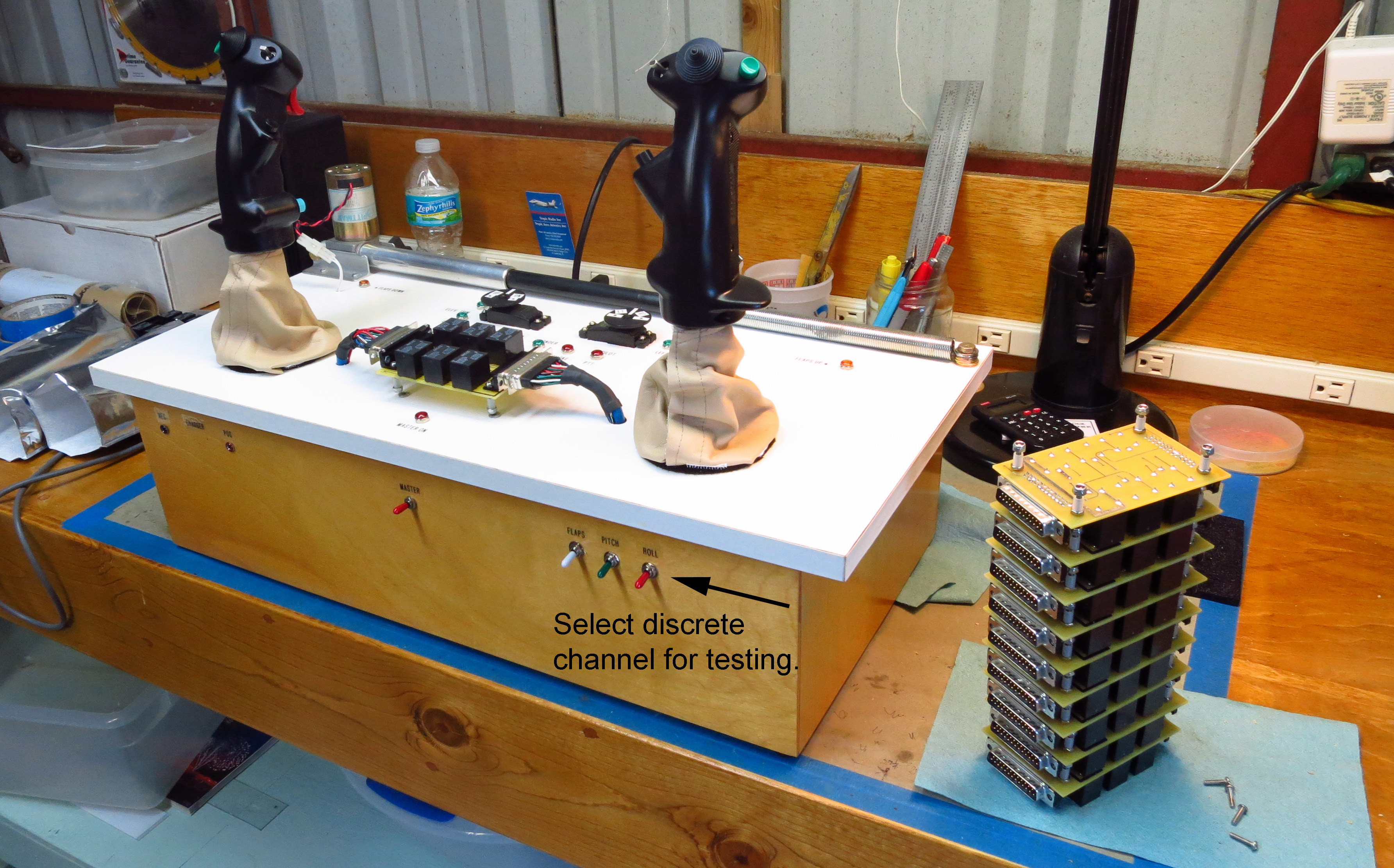
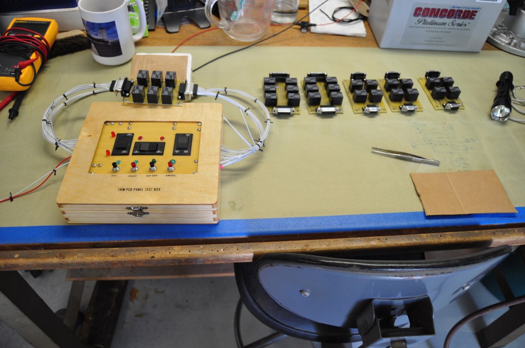
We also had to modify the test module for the separate inputs and added the three switches you see here so that we could isolate each function on the board.  Every TRB we manufacture is thoroughly tested with actual in-flight loads.

NEW! Beginning in September 2016, we began including spike suppressing diodes on the PCB for the relays, which should help increase the lifespan of your controlling switches (grip switches and flap switches), and will also minimize spurious EMF emissions caused by an inductive voltage spike arcing when switches are opened.

Modified Test Module

New Product: Flaps Full-Up Auto Stop Kit


(Click on picture for full size)

I’ve been flying RVs for 22 years now and something has always bothered me about the electric flaps. Don’t get me wrong, I love the RV flaps. It’s just that I get tired of holding the flap switch up when I’m on a go-around or when shooting touch-and-goes. So, if you’re like me, you probably listen for the telltale rumble the flap motor makes when the flaps are fully up. Either that or you glance out at the wing to see if the flaps are up—or both—and then let go of the switch. A distraction? Definitely!

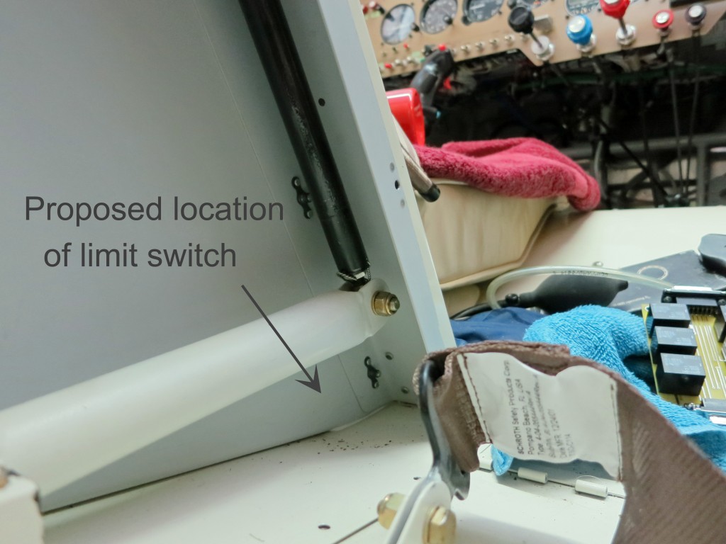
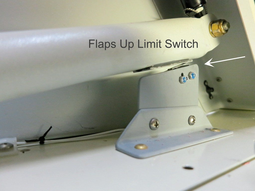
This looked like the best spot for the limit switch on my RV-6

Not to mention the safety aspect of messing with the flaps while you’re trying to add power, talk on the radio, clear for traffic and ask for a closed pattern, etc. And lately I’ve gotten into the habit of taking off with about 15° of flaps to save on tire wear.

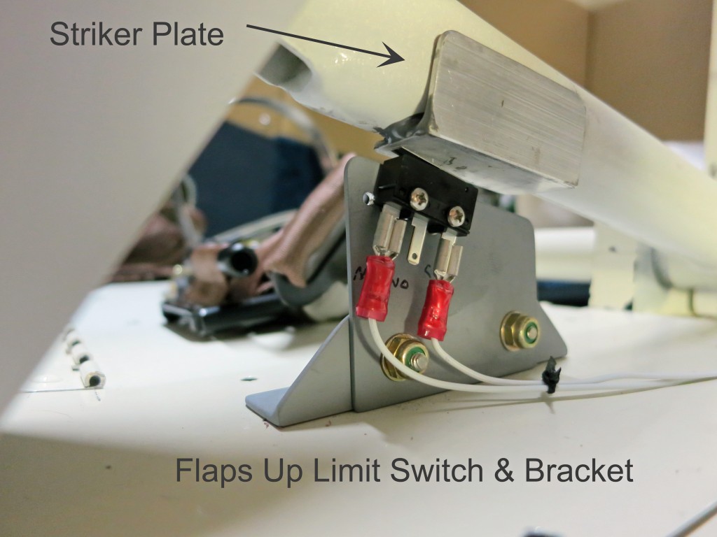
Here is the limit switch, bracket and striker plate mounted on my RV-6

Wouldn’t it be nice to just flip the flap switch up after takeoff and forget about the flaps? OK, now you’re in a nice safe climb or on downwind, go ahead and glance down at the flaps, make sure they’re up, and then, and only then, reposition the flap switch to neutral. Or just leave the switch up. You won’t hurt a thing.

Here’s another safety issue: I’ve been talking to some guys who have the flap switches on their Infinity grip. They mentioned that on occasion they would takeoff and flip their flap switch up and forget about it only to discover later in the flight that their flap motor had been running the whole time! I’m in favor of the ON (up) position on the flaps switch, but if you’re going to do that, you definitely want to add an up-limit microswitch to the circuit!

Limit switch from the right side.

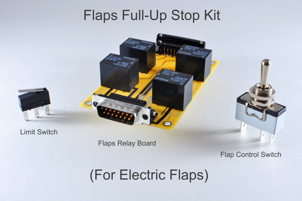
So, I’ve just developed a prototype kit and have been testing it in my RV-6—and I like it a lot! In keeping with the KISS principle, the kit consists of the bare essentials: a single pole double throw switch (ON-OFF-(ON)), a flaps-up limit switch, and a simple flap relay PCB board. This replaces my old DPDT ((ON)-OFF-(ON)) clunker in the panel. So now instead of spring-loaded UP and DN, the new switch stays UP and spring-loads DN. The power lead doesn’t go through the switch anymore, thus the flap amperage isn’t going through the switch, and in theory anyway, the switch should last longer.

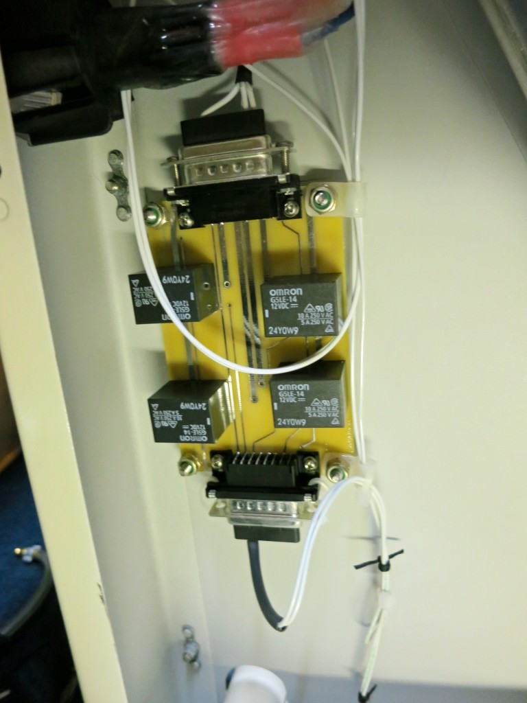
The key to this mod is the Flap Relay Board. The flaps-up limit switch will not work with the old DPDT switch as wired. Maybe you could find a way to make it work, but by far the simplest and best method in my opinion is to use the reversing relays like the ones in the Flap Relay Board. Especially for you Infinity grip guys who don’t need the flap motor amperage running through your grip! This way, there’s just a tiny bit of current (about 33 mA) flowing through your flap control switch and through your up-limit microswitch.

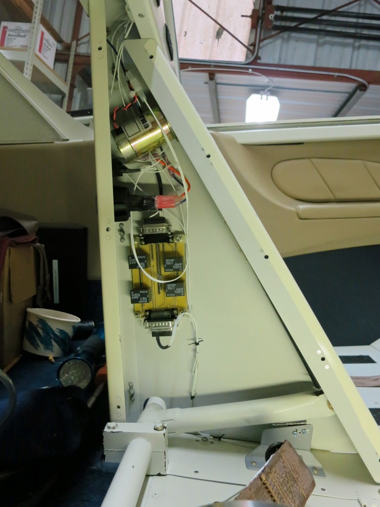
Flap Relay Board mounted on the left flap housing panel.

So you pull the old switch out of the panel, make a small modification to the wiring, find a place to install the limit switch, mount the Flap Relay Board (FRB) in the flaps enclosure, wire the new stuff up, and you’re ready to go. I think you can complete the mod in a day.

Closeup of the Flap Relay Board mounted in the flap housing

The attached photos are of the installation of the kit in my RV-6. There are slight differences in all the RV models, so it may be necessary to take a slightly different approach in your particular airplane.

I don’t know why it took so long for me to make this mod. This is definitely one of the neatest upgrades I’ve done to my airplane. I know a lot of you have already done this on your own airplane and therefore I’m sure you are enjoying the benefits. For those of you who haven’t, here’s an easy way to accomplish this hugely worthwhile mod!

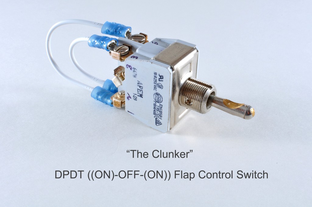
This is the old switch that came out for the mod.

So, I put the kit together and am introducing it as a new product which you can order here on the site. I have kits available now for immediate shipping.

Note: I was able to pull the flap-shaped lever off the old switch and used it on the new switch—see last photo. I made this lever out of a solid chunk of aluminum and worked it on the disk sander and scotchbrite wheel, then had it engraved.

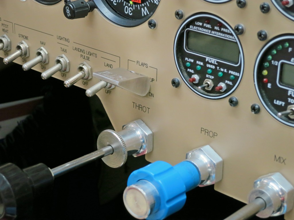
Flap Control Switch shown in the UP Position


Why Try our Trim Relay Boards/Hubs?

We’ve come a long way since I built my first RV in 1989, an RV-4.  Back then, it was a real hassle wiring my stick grip (a surplus USAF F-4 grip), trying to figure out how to get the wires through the stick and where to put the relays and how to route all of the wires for all of the functions available on the grip.  How in the world would you ever figure out which component failed if you had to troubleshoot this mess?  There wasn’t a lot of guidance or experience out there that you could tap into for ideas like there is today.

Around that time I started following Bob Nuckolls’ posts and reading his The AeroElectric Connection.  He certainly has brought a wealth of experience and information to the homebuilding scene, in my opinion.  Among other things, he introduced me to D-sub connectors and their various uses.  Today, D-sub connectors are ubiquitous on amateur-built aircraft.  In those days, D-subs were of the solder-cup variety and a real pain, but with the introduction of machined pins, which can be easily crimped to a wire and then inserted into the connector, the D-sub became an even more useful tool for making wiring harnesses.

In my latest build, an RV-6, I used D-subs throughout and found them to be especially effective in segmenting the wiring harness and to have disconnect points, especially at critical junctions such as the wing root.

So this brings me back to the stick grip.  I recently installed a new Infinity stick grip to the left stick on the RV-6.  I realized that what I really needed was a wiring hub somewhere in the system that would serve to centralize all of the various functions typically found in a grip.  This hub should be able to direct all of the inputs from the grip, process them, and then output the functions to the various components, all in one convenient unit.  So I set out to design a PCB where I could mount the relays needed for control of the trim servos, bring in the 12 volt power and grounds, and also provide a gateway for the signals from the various buttons on the grip.

The resulting trim relay boards and hub worked so well that I decided to make them available to other homebuilders and at a fraction of the cost of other relay boards out there.  This site is the result of that effort.

One of the huge advantages of the hub concept is what it brings to the maintenance troubleshooting process.  If you have a problem with a trim motor, for example, how would you troubleshoot it?  Besides the servo, it could also be the 4-way switch on the grip, it could be a relay, or it could be a broken wire.  Well, with the hub, you can remove the D-sub connectors at the hub and connect jumper wires for troubleshooting.  You can make these jumpers with machined pins or sockets crimped on the end of a short piece of AWG 22 wire.  Insert the jumpers onto the pins or sockets in the D-sub connectors and with an ohmmeter or voltmeter you can quickly figure out which component has malfunctioned.

Every trim relay board & hub that we manufacture is thoroughly tested with a test box and simulated load so that we can prove every circuit and relay.  For testing the flap/speedbrake relays, we use an actual flap actuator, weighted down, to simulate the normal operating loads on the circuit.

The finished product is an efficient and aesthetically pleasing design, tailored to the needs of the experimental homebuilder, and extremely small and lightweight.  I think you’re going to like it if you try it.

Which Trim Relay Board is Right for You?

The purpose of this post is to help you select which trim relay board is best for your situation.

If you have both elevator and aileron trim and you are considering actuating your wing flaps or speedbrakes from a stick grip, you definitely need the 3-channel trim relay board (TRB).  One channel is required for elevator trim, one for aileron trim, while the third channel is needed for the flaps or speedbrakes.

If you have a stick grip (like the Infinity shown here) and want to use all of the switches/buttons, you need the 3-channel TRB with the 15-pin connector.  The Infinity grip has a 4-way switch for elevator and aileron trim, a push-to-talk switch (the trigger) for radio transmissions, and 4 additional momentary buttons that can be used for a variety of functions.  Because of the number of grip functions, you actually need the 15-pin D-sub connector to serve as a hub/gateway for all of the switches.  You would not actually need the third relay channel, but it could be used as a backup in the event of a failure of one of the other relays.  To use the backup relay channel, however, you would need to re-pin the connectors accordingly.

Now if you have two maxed-out Infinity grips with all the bells and whistles, you will definitely want our newly introduced ‘The Ultimate,’ which is designed specifically for this situation.  With its two 25-pin D-sub connectors, there are plenty of pins for all the ground wires (you will probably have about 12 total) plus there are individual connections for each of the copilot stick functions that work in concert with the pilot’s functions.  And the 3 relay channels will accommodate two axis trim and flaps on both grips.

If, on the other hand, you have just one grip and you only have the 4-way and a maximum of three additional switches (such as the PTT, IDENT button, or autopilot CWS, for example), you could get by with the 2-channel TRB with the 9-pin connector.  The 9-pin D-sub connector is sufficient to handle all of these functions.  One advantage of using the 9-pin D-sub connector is that, if you should desire, you can actually have a disconnect for the stick grip located inside the stick tube, thereby allowing you to easily remove the grip for maintenance.  A pair of modified 9-pin D-sub connectors will fit inside the tube of the stick grip in most installations.

To review, if you have a 4-way and 3 or less additional pushbutton switches, you should choose the 2-channel TRB.  If you have a 4-way and more than 3 additional pushbutton switches or if you plan on having a flaps or speedbrake switch on your grip, you should select the 3-channel TRB.  If you have two grips of any flavor, you should try The Ultimate for maximum ease of wiring and accessibility.

Test Equipment/Simulator

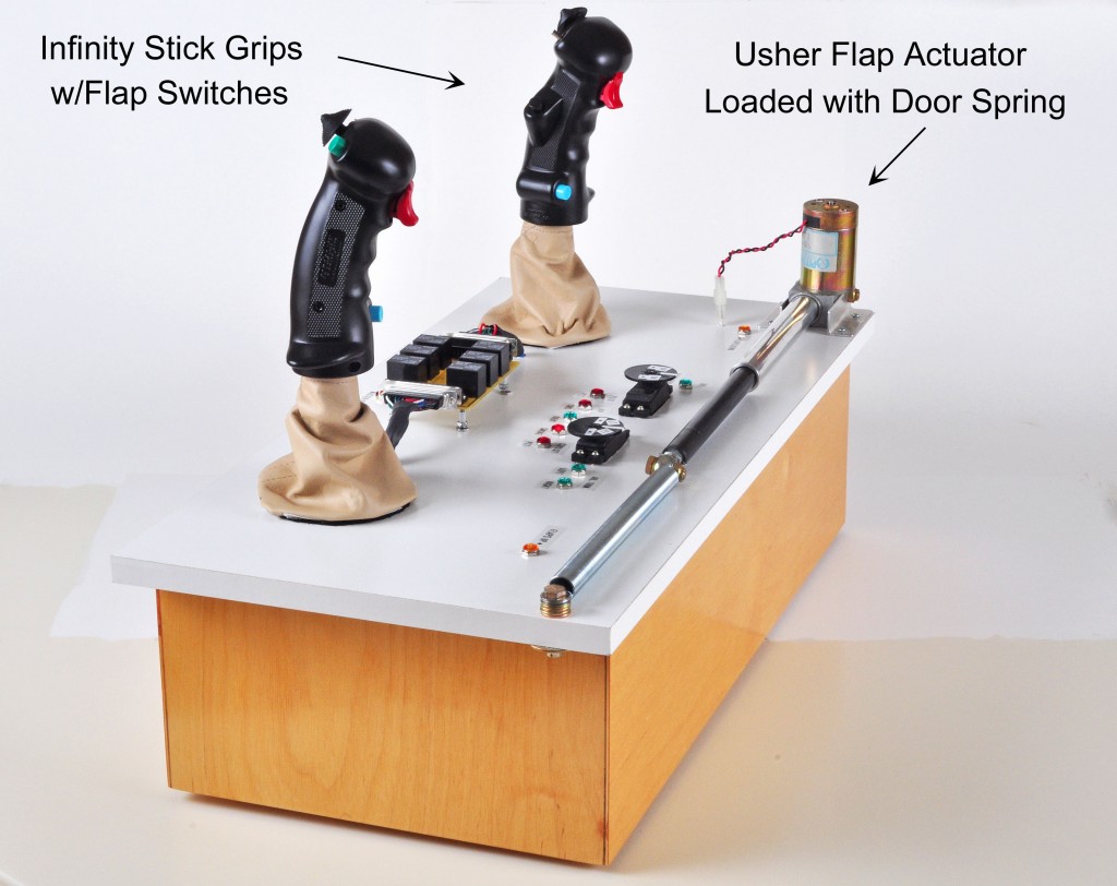
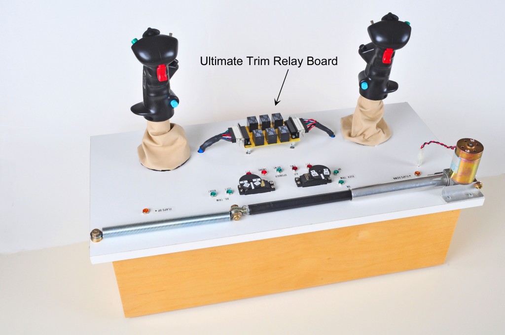
I finished up my Simulator for the new Ultimate Trim Relay Board and thought I would post some photos. I think it illustrates just how simple it is to wire two grips (with all the bells and whistles) using this hub concept—where all the wires from the grips go to the “input” D-sub connector and the “output” side is the gateway for all of the grip functions. Every one of the new relay boards gets a workout on the Simulator before it gets shipped (click on photo for enlarged version).

The Simulator

I have been getting excellent feedback from folks who have bought the relay boards. I wanted to emphasize that every relay board that I sell gets thoroughly tested before it gets shipped.

The flap actuator you see on the Simulator is an actual Usher Industries actuator as sold by Van’s Aircraft. I have done some testing with the flaps on my RV-6 to try to determine the amperage load during flaps operation. On the ground (or unloaded), amperage draw is slightly less than 1 amp. In flight, and within airspeed limits for flaps operation, amperage draw going down is between 3 to 5 amps, peaking towards the end of the cycle. It’s kind of hard to read the amperage because it varies so much as the flaps are moving, but on average the maximum load seems to be as flaps approach full down, and that’s about 5 amps or less. So I estimated that it would take about a 10 pound pull on the flap actuator to simulate (approximately) the load on the flaps in the airplane. I found a door spring, which you see here, that gave me about 10 pounds of force at 5″ of extension (flap actuator travel is 5 inches). The result is that I get almost the same amperage indications on the simulator as I do in the airplane, perhaps a little more on the simulator.

Actual Usher Flap Actuator


I used two old RC servos that I modified and loaded properly with resitors to simulate the electric trim servos we use on the RVs.

As it works out, this test rig will also serve nicely as a demonstrator at fly-ins, etc. Hope to see you with the Simulator someday soon at a fly-in somewhere!

And here is a photo of the original test equipment that I use for the smaller relay boards (lower right).

Anyway, I have trim relay boards available for most, if not all, grip configurations, so if you are approaching that phase of your build, please check out the web site and consider giving one of these a try.